Index-Velocity Guidance
The USGS has developed guidance to help ensure that data collected by USGS personnel are consistent and of high quality. The guidance consists of policy specified in technical memorandums (and referenced reports) and other best practices that are provided in published reports, papers, hydroacoustic updates, and information provided on this web site.
Policies
The USGS Techniques and Methods report, "Computing Discharge Using the Index Velocity Method" provides the primary source for guidance and policies on the installation and operation of index-velocity sites and the computation of streamflow records using the index velocity method. In addition, the Office of Surface Water (OSW) has issued policy memos that address methods or issues not covered in Levesque and Oberg (2012)- OSW Technical Memorandum 2015.05 Minimum requirements for documenting stage-area and index-velocity ratings for computation of streamflow records using the index velocity method. Several resources related to the implementation of this policy are available:
- Table summarizing the requirements for documenting stage-area ratings and index-velocity ratings.
- Documentation examples for index-velocity streamgages.
- OSW Technical Memorandum 2014.08 Policy for the timely correction of time-series data displayed on the NWISWeb. This memo includes policy on storing 1-min index velocity data in NWIS.
Other Useful Reports
Computation of Discharge Using the Index-Velocity Method in Tidally Affected Areas by C. A. Ruhl and M. Simpson, 2005, U.S. Geological Survey Scientific Investigations Report 2005-5004
Feasibility of Acoustic Doppler Velocity Meters for the Production of Discharge Records from U.S. Geological Survey Streamflow-Gaging Stations by S. E. Morlock, H. T. Nguyen, and J. H. Ross, 2002, U.S. Geological Survey Water-Resources Investigations Report 01-4157
Acoustic velocity meter systems by Antonious Laenen, 1985, U.S. Geological Survey Techniques of Water-Resources Investigations, book 3, chap. 17
Best Practices
Summary of the Computation of Discharge Using Index-Velocity Methods
The water velocity measured by a hydroacoustic current meter in a portion of a river can be used as a surrogate or "index" for the mean-channel velocity. The following is a summary of the computation of discharge using index-velocity methods.
- A hydroacoustic current meter is installed in a river. The current meter measures water velocities in a portion of the channel. The water velocity measured by a hydroacoustic current meter that will be used to compute mean channel velocity is called the "index velocity." Hydroacoustic current meters commonly used for index velocity applications include acoustic velocity meters, acoustic Doppler velocity meters, and acoustic profilers (the Instruments page contains a description of these hydroacoustic current meters).
- Velocity and various current meter performance and quality-assurance data are recorded by the current meter in internal memory or are logged by an electronic data logger (EDL). The current meter and EDL are often interfaced using the SDI-12 (serial digital interface at 1200 baud) communications protocol. River stage must also be measured and recorded. Some hydroacoustic current meters can measure stage acoustically, or stage can be measured by a separate stage sensor.
- A cross-section, called a "standard cross section" is surveyed near the current meter installation. The standard cross-section is used to develop a relation between stage and channel area, called a "stage-area rating." The channel area computed from the stage-area rating will be used, with mean-channel velocity, to compute discharge. A USGS program called AreaComp has been created for the development of stage-area ratings ( Download AreaComp).
- Discharge measurements are made while stage and index velocity are measured and recorded. Stages and index-velocities measured during the discharge measurement are averaged. The stage-area rating is used to compute channel area (A) from the average stage (S). The measured discharge divided by the channel area computed from the stage-area rating yields average mean velocity. The channel area is always computed at the standard cross-section, using the stage-area rating.
- Each discharge measurement produces a value mean channel velocity (V) and index velocity (Vi). After multiple measurements have been made, a relation between V and Vi is developed; the relation is called an "index-velocity" rating. Index-velocity ratings are commonly developed by first creating scatter plots with V as the ordinate (y axis) variable and Vi as the abcissa (x axis) variable. A line or curve is fitted scatter plot points. The line or curve is
the index-velocity rating. Many index-velocity ratings can be represented as a mathematical formula (the equation of the plotted line or curve). Single-parameter ratings have one independent variable (Vi) used to compute V. Index-velocity ratings can also have more than one independent variable (such as Vi and S) and are called multi-parameter or complex ratings. See link to index velocity rating flowchart below.
- Discharge (Q) is computed from the equation Q = VA. V is computed from application of the index-velocity rating to Vi and A is computed from application of the stage-area rating to S.
Index Velocity Rating Flowchart
- Levesque and Oberg (2012) developed a flowchart to aid in the development of index velocity ratings. This flowchart (and the guidance provide in the Techniques and Methods report should be followed when developing index-velocity ratings.
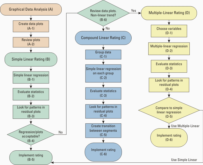
Meter Maintenance
- Check bolts, fittings, cables and connectors for excessive corrosion or wear;
- Remove growth (i.e. zebra mussels, algae, barnacles) from mount during periodic maintenance;
- Clean transducers periodically to remove build up of algal growth and other organisms. Anti-fouling paint and pepper extracts can reduce bio-fouling of transducers.
- Do not use abrasives or scouring pads on transducers and inspect for nicks, dents, etc.;
- Inspect cable when you service instrument, look for wear or breaks in the jacket around the cable;
- Inspect connector and pins periodically and grease pins with silicone, especially in corrosive waters (saline, low pH, etc.);
- When opening an instrument for maintenance, work in as clean and dust-free environment as possible. Follow the step-by-step instructions in the manual for your instrument. Check for a desiccant bag and replace it unless you are sure it is completely dry;
- Periodically check O-rings on a schedule in accordance with manufacturer recommendations. O-rings should be free of cuts, scratches, or foreign matter. Replace flattened O-rings and lubricate lightly with silicone grease. Don't overdo it! Check O-ring grooves in head and end-cap and make sure they free of foreign and that they are not damaged.